
Accidentally wiping the bootloader on a 3D printer motherboard—or corrupting the firmware during an interrupted flash—can render your expensive 3D printer mainboard completely unresponsive. Standard SD card flashing won’t work if the bootloader is erased, and USB DFU mode can be finicky on custom ARM Cortex microcontrollers like the STM32G0B1RE (BTT SKR Mini E3 V3.0) and STM32H723 (BigTreeTech SKR 3 V3.0).
The good news? You do not need to buy a dedicated ST-Link V2 hardware programmer to unbrick your mainboard. If you have a Raspberry Pi (Pi 3, Pi 4, or Pi 5) running Klipper or OctoPrint, you can unbrick, erase, and re-flash raw bootloaders directly using a simple 5-wire SWD (Serial Wire Debug) GPIO bitbang interface with OpenOCD.
Download OpenOCD SWD Scripts & Schematics
Access raw rpi-swd.cfg configuration scripts, KiCAD circuit schematics, and pinout diagrams directly on GitHub:
⭐ View Repository on GitHub (shahzad15/3DPrinterMods-5Wire-SWD-RPi-Bitbang-Flashing) →

Shop BTT Mainboard Deal →

Shop Raspberry Pi 4 Deal →
🔌 1. The 5-Wire SWD Vero Board Setup & EDA CAD Circuit Schematic
To establish a low-level debug interface between the Raspberry Pi and the BigTreeTech motherboard (SKR 3, SKR Mini E3 V3.0, SKR 2, or Octopus), connect 5 female-to-female Dupont jumper wires according to the hardware circuit diagram below:
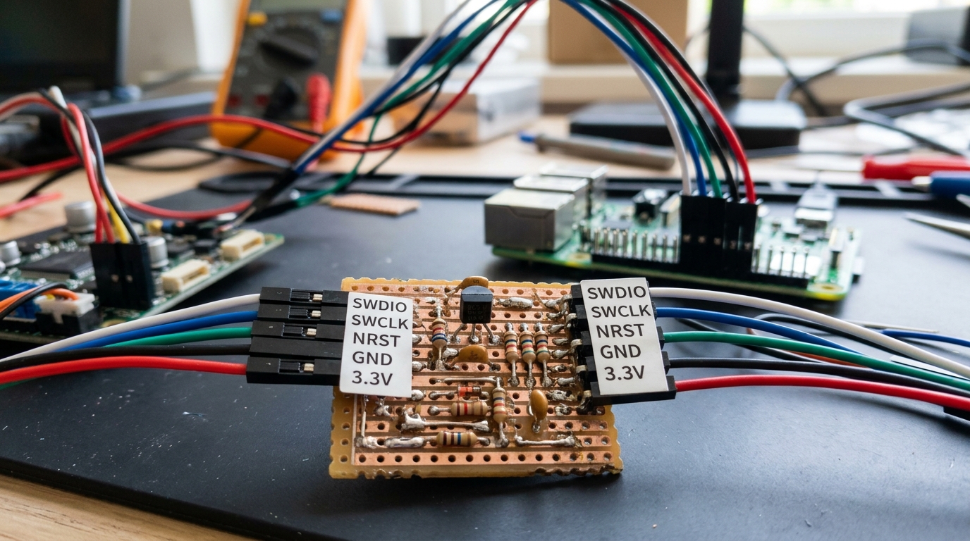
Realistic Hardware Prototype: Soldered Vero Board Module with Transistor, Resistors & Header Labels (SWDIO, SWCLK, NRST, GND, 3.3V)
Professional KiCAD / EDA Circuit Schematic Diagram:
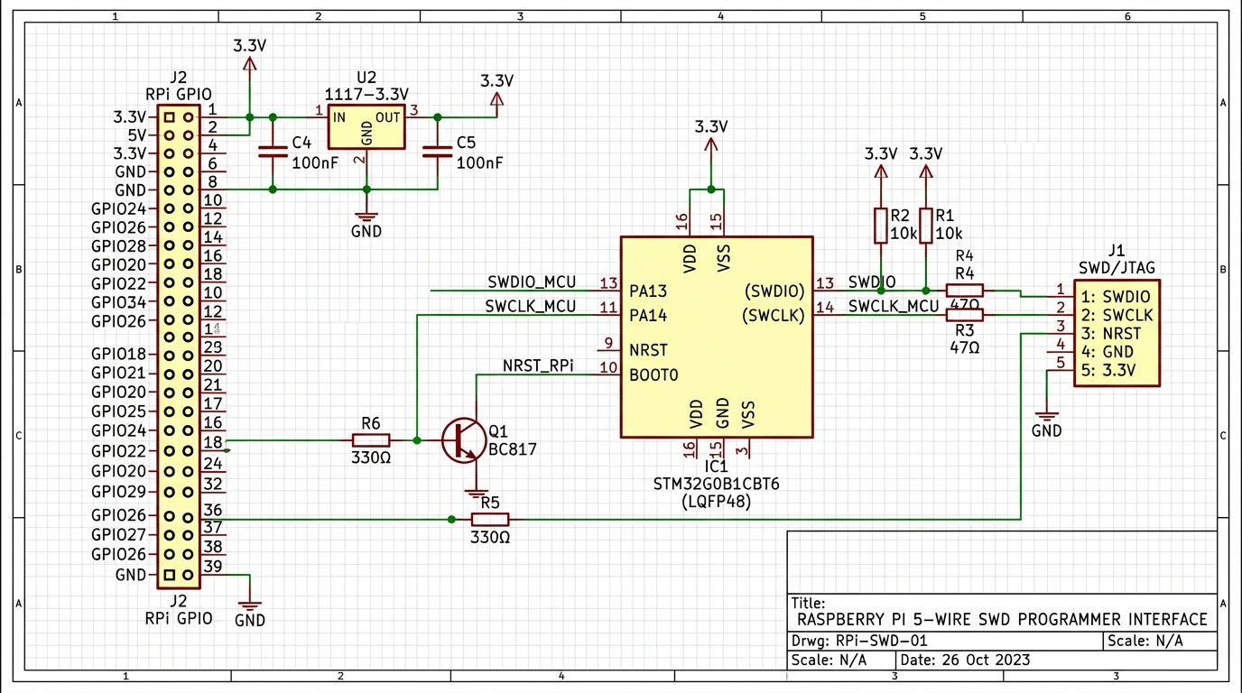
EDA Circuit Schematic Diagram: STM32G0B1 MCU, 5-Pin SWD Header (J1), RPi GPIO Header (J2), BC817 Transistor (Q1), and 10k Pull-Up Resistors
🛠️ 2. Installing OpenOCD on Raspberry Pi
Log in to your Raspberry Pi via SSH terminal and install OpenOCD alongside the required GPIO hardware libraries:
# Update repository indices and install build dependencies
sudo apt-get update
sudo apt-get install -y build-essential libtool autoconf automake pkg-config libusb-1.0-0-dev openocd
📄 3. Creating the OpenOCD SWD Config (rpi-swd.cfg)
Create a custom OpenOCD configuration file on your Raspberry Pi named rpi-swd.cfg to define the GPIO bitbang mapping for BCM2835 / BCM2711 chips:
# rpi-swd.cfg - Raspberry Pi 5-Wire SWD Bitbang Configuration
adapter driver bcm2835gpio

# BCM2835 / BCM2711 GPIO Base Address
bcm2835gpio speed_coeffs 236193 60

# Define SWD Pins (GPIO Pin Numbers)
bcm2835gpio swd_nums 25 24
bcm2835gpio srst_num 18

# Transport protocol
transport select swd

# Define Target MCU (STM32G0 for SKR Mini E3 V3, STM32H7 for SKR 3 V3)
source [find target/stm32g0x.cfg]

# Adapter Speed (kHz)
adapter speed 1000
Note: If unbricking a BTT SKR 3 V3.0 (STM32H723), replace source [find target/stm32g0x.cfg] with source [find target/stm32h7x.cfg].
🚀 4. Executing Bootloader Flash & Unbricking
With wires connected and OpenOCD configured, execute the following commands in SSH terminal to halt the microcontroller, erase flash memory, and flash the official BigTreeTech bootloader binary (bootloader.bin):
# Step 1: Start OpenOCD target session
sudo openocd -f rpi-swd.cfg

# Step 2: In a second terminal window, connect via Telnet
telnet localhost 4444

# Step 3: Inside OpenOCD Telnet Prompt:
reset halt                            # Halt ARM core
stm32g0x unlock 0                     # Unlock write protection if locked
flash erase_sector 0 0 last           # Full flash chip erase
flash write_image erase bootloader.bin 0x08000000 # Write bootloader at base address
reset run                             # Reset MCU into fresh bootloader
Want to flash firmware wirelessly without opening your printer enclosure? Read our standalone guide: Wireless SWD Firmware Updates & Unbricking over Wi-Fi (ESP32 Bridge Guide) →
🏆 Summary & Verification
Once reset run executes, your BigTreeTech mainboard status LED will begin blinking normally. Insert your MicroSD card containing firmware.bin (Marlin or Klipper), power cycle the printer, and the fresh bootloader will automatically flash the firmware! 5-wire SWD bitbang via Raspberry Pi is the ultimate tool in any 3D printing maker’s toolkit to unbrick mainboards without buying extra hardware programmers.